Been a while, I know. November was brutal. Somehow I have more work despite fewer credits. Built some CubeSat reaction wheels though, which was pretty cool. Also managed to fix up the simulation software a bit more.
I added real orbital dynamics this time around. Previously I had been propagating the time from the simulation time-step and using it combined with time since periapse to get the new position and velocity for my magnetic field and gravity gradient calculations. Not very accurate, but an appropriate method for a sim based on an undergrad class where we spent far more time on attitude dynamics than orbital dynamics. Now, however, I’m directly using the position and acceleration vectors resolved in the ECI frame with Newton’s EOM. In essence, I’m integrating the equations of motion in ode45 with Euler’s attitude dynamics equations to propagate the orbit. This allows for more orbit flexibility as well, since now I can model thrust very easily. It is just another term added to the EOM.
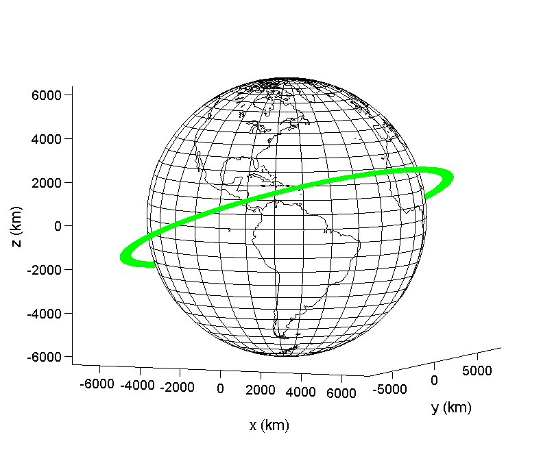
You can see in Figure 1 below the effect of properly integrating the orbital dynamics on both the 3D trajectory plot and the attitude control torques of the spacecraft. The orbit looks about the same, and the control torques appear to be of the same order of magnitude as well.

")
Figure 1: No Thrust Simulation, Trajectory & Attitude Control Torques
Figure 2 shows what happens when we add a continuous thrust force of 1 mN in the direction of the instantaneous velocity vector. The 3D trajectory plot tells the real story; the orbit itself starts to change. The thrust along the velocity vector ensures that the orbit plane does not change, but the altitude does appear to change. The control torques actually look to be around the same in magnitude, except for control torque about the 1 axis, which drops by a factor of about 2. This could be due to decreased gradient torque about the 1-axis at the farther altitudes in the thrusting case. The altitude change can be seen by the “thicker” line in the trajectory in Figure 2.


Figure 2: 1 mN Thrust Simulation, Trajectory & Attitude Control Torques
In Figure 3, the effect of the thrust along the velocity vector is more pronounced since I ran the simulation for 60 orbits rather than 30 orbits. There is actually a really good reason for this behavior, and it has to do with angular momentum. The trajectory of the spacecraft remains planar because the perturbing force is along the instantaneous velocity vector; so the direction of the angular momentum vector does not change. The angular momentum magnitude changes, because angular momentum h = r × v , and v is changing in magnitude due to the force acting along it. The angular momentum direction does not change since the perturbing force does not change the direction of the velocity vector. This is why the trajectory remains in the same plane. It is an interesting result, and a pretty cool way of modeling basic thrust. It would be cool to have the simulation be configurable such that you can define a thrust relative to the velocity vector. That should be pretty doable if I’m careful with my vectors.

Figure 3: 1 mN Thrust Simulation, Trajectory Over 60 Orbits
These are some basic results from the latest sim update. In addition to allowing more thrust configurations, I want to investigate the causes of attitude dynamics changes with thrust further. Ideally I would couple thrust with the attitude dynamics by including some thrust induced torque since thrust likely will not be exerted exactly on the cg of the spacecraft.
Note: I updated this post to add Figure 3 and the related info.

Leave a comment