First cut, second post. Last time I mostly talked about the background and inner workings of the attitude dynamics simulation I’ve upgraded. Now I’ll talk a bit more about the advanced stuff that’s included.
I mentioned the mechanisms that allow our little CubeSat to orient itself to where we want, and promised to talk about how that actually happens. For a 3U CubeSat engineers usually use magnetic torque rods and/or reaction wheels.
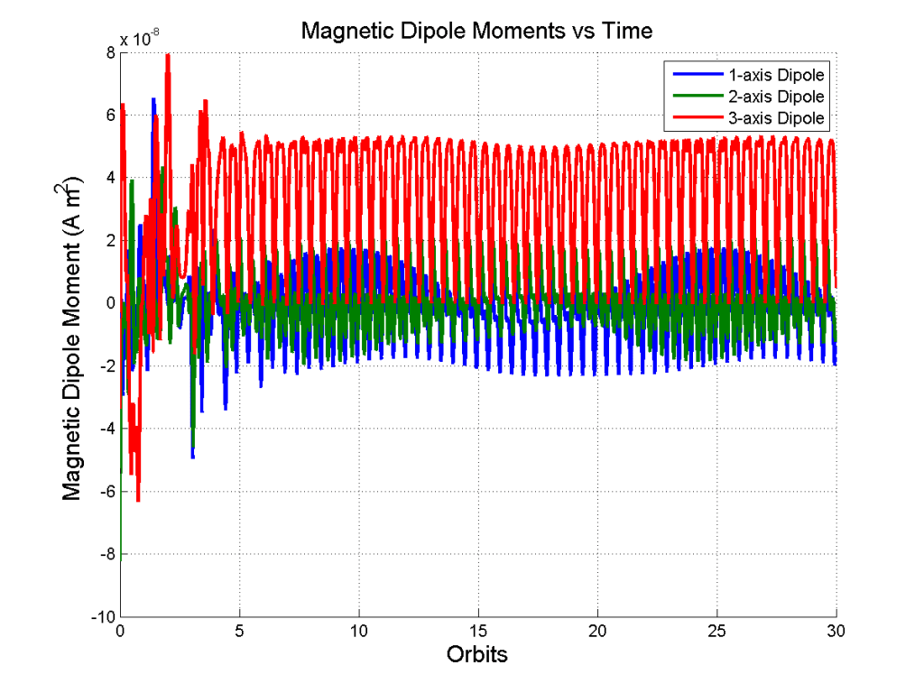
Magnetic torque rods are essentially solenoids (copper wire wrapped in a cylindrical shape, usually around a ferromagnetic core) that react with the Earth’s local magnetic field. When current runs through the copper wire, a magnetic dipole moment is created, and this dipole moment reacts with the Earth’s local magnetic field, which induces a torque on the spacecraft.
The simulation as it stands uses magnetic torque rods as it’s actuator. I’ve modeled them in the config file via the number of turns of wire in the solenoid and it’s cross sectional area. The way the simulation works, the control law calculates a required torque to stabilize and orient the spacecraft at each timestep. This required torque is used with the properties of the torque rods (number of turns and area) to get the required magnetic dipole moment associated with the required torque. We can even get the current draw for each individual torque rod!


Note: These plots correspond to the same simulation configuration and initial conditions from my last post.
Each plot has 3 sets of values; each color represents a different one of the axes of the spacecraft body reference frame. Its clear that the control system never really gets a break here since it has to store the change in angular momentum required to re-orient the spacecraft.
I’d also like to add reaction wheel functionality to my simulation, so that a user could potentially choose between two actuation methods, or even use both. I need to do some more investigating into wheel orientations, however, since reaction wheels often have a wheel or two aligned on a diagonal for redundancy, so that one spare wheel can influence torques about multiple spacecraft body axes.

Leave a comment