
Success! For now…
The first cut of my attitude dynamics simulator upgrade appears to work. There wasn’t too much substantive change in terms of the control theory in this upgrade – I mostly re-organized the configuration scripts and made them more modular for easy editing and modelling of different spacecraft. I also added a progress bar to make it more user friendly (this is probably the bit I was most excited about on this upgrade to be honest). Check out the simulation background info below if you’re interested, or jump straight into the plots further down.
Simulation Background
First off, I’ve written this simulation in MATLAB. Yes I know, “not a real programming language” blah blah, but MATLAB is really fantastic for anything dynamics related because using matrices is so damn easy; you don’t need to import libraries and figure out APIs, its just * for matrix multiplication and ‘ for transpose. Additionally, numerical integration of non-linear ODEs is built in with ode45 and a couple of other solvers, so once again there is no hunt for solver libraries or unnecessary implementation.
The basis of all of my simulation work is reasonably simple when you realize the core of it is always Euler’s Equation for Rotational Dynamics. Since we’re simulating the orientation of a spacecraft as it orbits the Earth, we’re concerned with how it rotates in 3 dimensions. Euler provides us with a nice set of matrix differential equations that we can (relatively) easily mold into state space form, which is required for use with MATLAB and most numerical solvers. Using state space form allows us to set an initial angular velocity and position and then let MATLAB calculate the changes in angular velocity and position due to disturbances and our controller.
I’m not going to get too deep into the math here, but as you can imagine most of the modelling of the spacecraft and scenario occurs in the external torque term as well as the inertia matrix term of the equation. I’ve set it up such that the external torque term contains the control torque (dictated by the control law) as well as the gravity gradient torque. Gravity gradient is the main disturbance for this model, and since I am modelling CubeSats with my inertia matrix, this is fairly appropriate. CubeSat’s (especially 2U and 3U) tend to feel the effects of gravity gradient due to their small mass and prolonged shape.
The simulation allows for multiple controller configurations, the user can choose any combination of Proportional, Derivative, and Feed Forward control. Although, as any control theory professor will tell you, you never choose pure Derivative control since you’d end up just differentiating sensor noise which is completely meaningless and can cause instability. Feed Forward and Proportional control can be quite useful on their own, however.
Plots
Finally, plots! The following plots show the spacecraft orientation, expressed as a quaternion, followed by the angular velocity of the spacecraft relative to some inertial frame and resolved in the body frame. They model a fairly standard 3U CubeSat (10 cm x 10 cm x 30 cm, 30 kg) which starts at some initial quaternion offset [0; .5; 0; √(1-0.5²)] and angular velocity [.002; .002; .002].
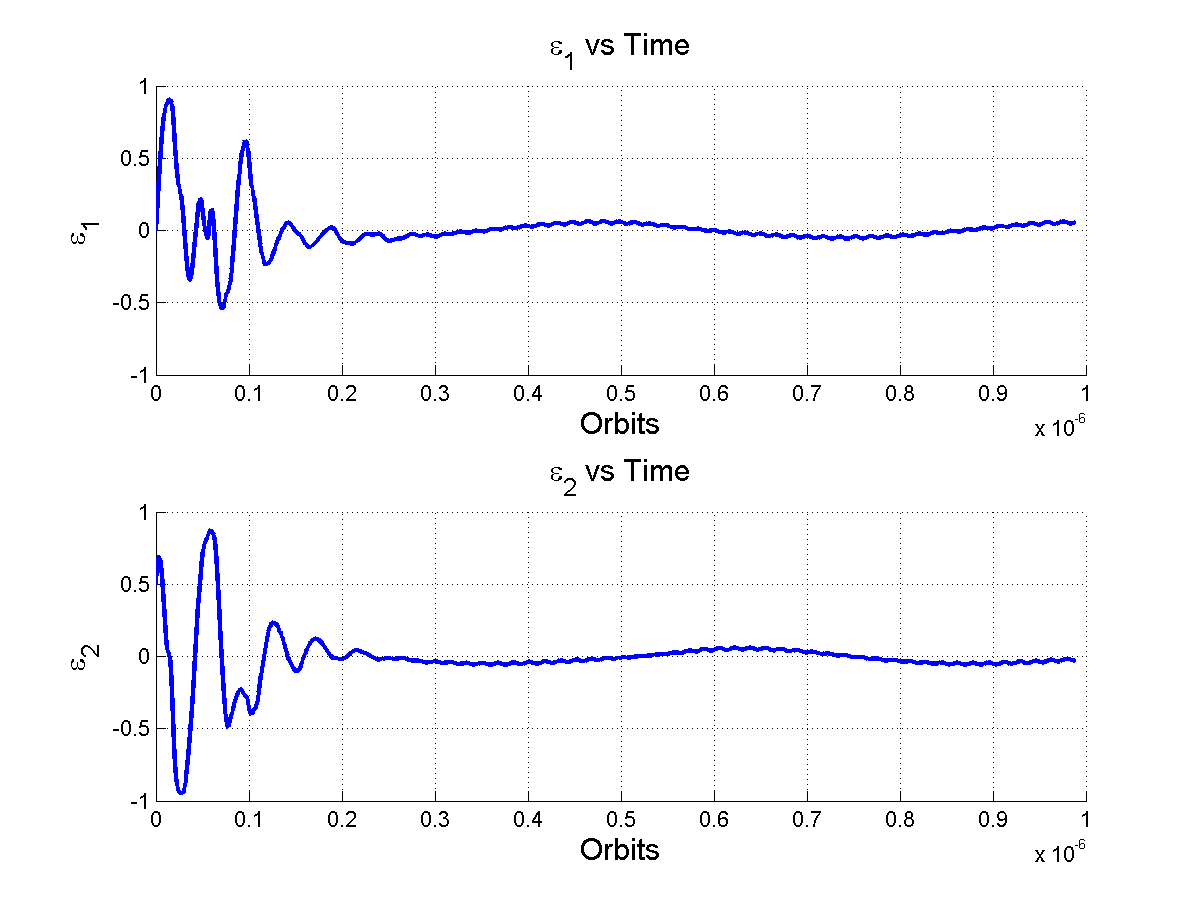
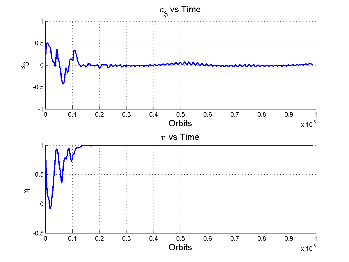
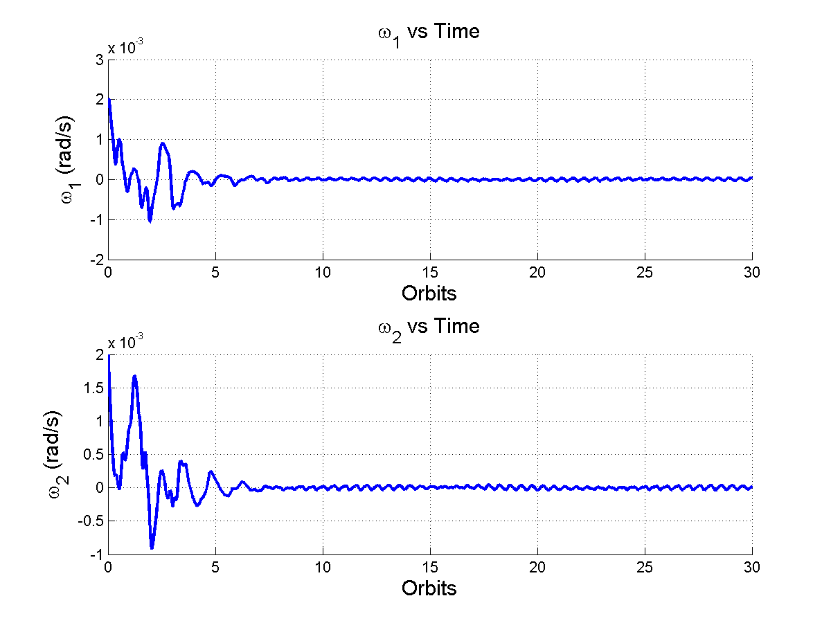
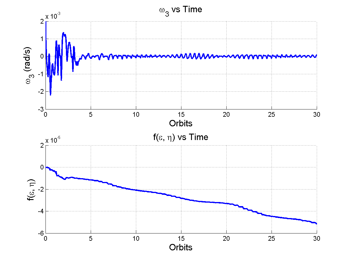
Figures 1 and 2 show us some basic information about what the spacecraft is doing; we see that the orientation converges around the quaternion [0; 0; 0; 1], which is the desired orientation, and that the angular velocity drops to zero within about 7 orbits. The last plot also shows us an estimation of the simulation error due to numerical drift in MATLAB’s calculations. Ideally the last plot would be a straight line where f(ε,η) = 0 ∀ t (where t is expressed in Orbits), but since MATLAB is numerically approximating here, we get some small errors.
So overall, these basic plots are good news: the spacecraft is able to orient itself into the desired position and stay stable even though it starts off spinning in a different direction. But what mechanisms allow the spacecraft to actually rotate to orient itself? And how do we quantify that?
I’ll get into those questions in the next post.

Leave a comment